
Computer Networking: MAC Addressing and ARP
Media Access Control Address
- Identifies the physical network interface of a host
- Hexadecimal addressing:
0-F - 48 bits (6 bytes)
- Hexadecimal addressing:
- In early, primitive networks, computers were often on a shared "media" and needed a way to address each other
- On a shared medium, all computers will receive the data
- Network interfaces are supposed to (see promiscuous mode) ignore anything not addressed to them
- This behavior still exists to this day
 <------------------------------------------------- 6 OCTETS ---------------------------------------------------->
                                                    48 BYTES
 __________________ __________________ __________________ __________________ __________________ __________________
|                  |                  |                  |                  |                  |                  |
|      OCTET       |      OCTET       |      OCTET       |      OCTET       |      OCTET       |      OCTET       |
|     8 BITS       |     8 BITS       |     8 BITS       |     8 BITS       |     8 BITS       |     8 BITS       |
|     1 BYTE       |     1 BYTE       |     1 BYTE       |     1 BYTE       |     1 BYTE       |     1 BYTE       |
|                  |                  |                  |                  |                  |                  |
|    00 thru FF    |    00 thru FF    |    00 thru FF    |    00 thru FF    |    00 thru FF    |    00 thru FF    |
|                  |                  |                  |                  |                  |                  |
'__________________'__________________'__________________'__________________'__________________'__________________'
 |                                                      | |                                                      |
 |                                                      | |                                                      |
 |______________________________________________________| |______________________________________________________|
                             |                                                        |
                             |                                                        |
        Organizationally Unique Identifier (OUI)                         Network Interface Card (NIC)
                         3 OCTETS                                                 3 OCTETS
Broadcast Domain vs Collision Domain
- In the diagram below, the broadcast domain is designated as the entire Local Area Network (LAN)
- When a host sends a layer 2 broadcast --
FF:FF:FF:FF:FF:FF-- every host on the LAN receives it
- When a host sends a layer 2 broadcast --
- In the diagram below, the collision domain is designated as the shared media between hosts, the cable
- Traffic from both switches can be on the cable in duplex, and therefore has the possibility to collide
                     _________________________________
                    |                                 |
                    |                                 |
 .----------------> |             SWITCH 1            |
 |                  |                                 |
 |                  |                                 |
 |                  '_["]_["]_["]_["]_["]_["]_["]_["]_'
 |                     |   |   |   |   |   |       |
 |                     |   |   |   |   |   |       |
 |                    PC0  |  PC2  |  PC4  |       |
 |                         |       |       |       |
 |--------------->        PC1     PC3     PC5      |
 |                                                 |
 |                                                 |
 |  BROADCAST               LOCAL AREA             |            COLLISION
 |     DOMAIN              NETWORK (LAN)           | <--------- DOMAIN
 |                                                 |
 |                                                 |
 |--------------->    PC6     PC8                  |
 |                     |       |                   |
 |                     |  PC7  |  PC9              |
 |                     |   |   |   |               |
 |                     |   |   |   |               |
 |                   __|___|___|___|_______________|__
 |                  | '-' '-' '-' '-' '-' '-' '-' '-' |
 |                  |                                 |
 '----------------> |             SWITCH 2            |
                    |                                 |
                    |                                 |
'_________________________________'Address Resolution Protocol
- IP addressing is the primary way we identify hosts belonging to a network
- It's easier to remember than a MAC address
- When preparing to transmit data, to another host on the network, the sender needs to know two things:
- The recipient IP address
- The recipient MAC address
- ARP is the protocol that is used to look up a MAC address for any given IP address
- Send a layer 2 broadcast --
FF:FF:FF:FF:FF:FF
- Send a layer 2 broadcast --
Who has
192.168.1.10?
Tell192.168.1.13
-
- Then,
192.168.1.10should respond to192.168.1.13with its MAC address.
- Then,
When we abstract things with the OSI Model or the TCP/IP Model, there's one practice I dislike
We tend to say, "MAC addresses are for communicating at layer 2".
Conveys that computers can distinctly communicate with one another using strictly MAC addresses
That's just simply not a true, as a fully formed packet must be transmitted between hosts
The diagram below is used to reinforce that point. A computer doesn't communicate with just a MAC or just an IP. It's a fully assembled frame encapsulated from the application layer to the data link layer. The TCP packet is encapsulated in the IP packet, which is encapsulated in the Ethernet frame.
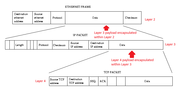
Example shows how multiple segments of networking data are nested to form a complete Ethernet frame
https://tldp.org/LDP/tlk/net/net.html
Routing and Switching Flowchart
Computer Networking Flowchart (benheater.com)
Virtual Local Area Networks
- VLANs are a layer 2 concept
802.1qis the protocol that defines VLAN- The
802.1qheader is injected into the Ethernet frame of a packet - A
802.1qID can range from1to4094, due to limits on the maximum size of an Ethernet frame
- Not going to do a deep dive on VLANs, but hope to clear some things up