
Configuring 802.1q VLANs
Network Diagram
VLAN IDs and their IP blocks do not need to align (e.g. VLAN 10 = 10.10.10.0/24 or VLAN 100 = 10.100.100.0/24), I've only done this to make it easy to remember.
             . ```````  .
          ,"      ^       ",
         :        |         :
         : <---FIREWALL---> :
         '        |         '
          '.      v       .'
             ' .______. '
   WAN - igb0 ["]    ["] igb1 - LAN (Native) ------- 172.16.32.1/24
                      |      igb1.10 (VLAN 10) ----- 10.10.10.1/24
                      |      igb1.12 (VLAN 12) ----- 10.12.12.1/24
                      |      igb1.100 (VLAN 100) --- 10.100.100.1/24
                      |      igb1.107 (VLAN 107) --- 10.107.107.1/24
                      |      igb1.1028 (VLAN 1028) - 10.128.128.1/24
                      |      igb1.3000 (VLAN 3000) - 10.30.30.1/24
                      |                                                          ,-------------------------,
            .---------'                                                          |                         |
            |                                                                    |  igb0 = WAN interface   |
            |                                                                    |  igb1 = LAN interface   |
            |                                                                    |                         |
            |     _____________________________________________________          |  U = Untagged           |
            |    | \                                                   \         |  T = Tagged             |
            |     \ \     MANAGED SWITCH  -  192.168.0.5/24 (Static)    \        |                         |
            |      \ \___________________________________________________\       |  PVID = Port VLAN ID    |
            |       \|___[1]___[2]___[3]___[4]___[5]___[6]___[7]___[8]___|       |                         |
            '-------------'     |     |     |     |           |     |            |  bond0 = Server NICs    |
                        PVID  PVID  PVID  PVID  PVID  PVID  PVID  PVID           |          in software    |
                          1    100   100   100   100   10    10    12            |          bond           |
                         ===   ===   ===   ===   ===   ===   ===   ===           |                         |
                          U     U     U     U     U     U     U     U            '-------------------------'
                          1    100   100   100   100   10    10    12
                         ===   ===   ===   ===   ===   ===   ===   ===
                          T     T     T     T     T           |     T
                         10    10    10    10    10           |    107
                         12    107   107   107   107          |    1028
                         100   1028  1028  1028  1028         |     |
                         107   3000  3000  3000  3000         |     '---------,
                        1028    |     |     |     |           |         ,-----'-----,
                        3000    |     |     |     |           |         |  ACCESS   |
                               ["]   ["]   ["]   ["]          |         |           |
                                '-----'--.--'-----'           |         |   POINT   |
                      ___________________|______________      '----,    '._________.'
                     |\ VIRTUALIZATION   |    SERVER     \         |          |
                     | \                 |                \        |          '--- SSID: LAB_DEVICES [VLAN 1028]
                     |  \             [bond0]              \       '---,           SSID: IOT_LAN     [VLAN 107]
                     |   \               '----,             \          |
                     |    \                   |              \         |      _____________         ,-------,
                     |     '__________________________________'        |     |    WIRED    |        |       |
                     |     |                  |               |        |     |      PC     |        | smart |
                     |     |                  |               |        '-----:-------------:        | phone |
                     |     |        __________|_____          |               \   VLAN 10   \       |       |
                     |     |       |\ _______________\        |                '-------------'      '-------'
                     |     |        \| VIRTUAL SWITCH |       |                                    connected to
                     |     |         '--|-----|----|--'       |                                     IOT_LAN (VLAN 107)
                     |     |            |     |    |          |
                     \     |          [VM1] [VM2] [VM3]       |
                      \    |          VLAN  VLAN  VLAN        |
                       \   |          1028  3000   10         |
                        \  |                                  |
                          \'__________________________________'
Port Configurations
| PORT | 1 | 2 | 3 | 4 | 5 | 6 | 7 | 8 |
| PORT VLAN ID |
1 | 100 | 100 | 100 | 100 | 10 | 10 | 12 |
| UNTAGGED |
1 | 100 | 100 | 100 | 100 | 10 | 10 | 12 |
| TAGGED |
10 100 107 1028 3000 |
10 107 1028 3000 |
10 107 1028 3000 |
10 107 1028 3000 |
10 107 1028 3000 |
n/a |
n/a |
107 1028 |
Managing the Switch
The switch is statically configured with 192.168.0.5/24
In order for the network administrator to manage the switch and configure ports, VLANs, and more, the network administrator can:
- Plug their computer into port 6
- Statically configure their computer in the same subnet (e.g. 192.168.0.25/24)
- Then open their web browser and go to
http://192.168.0.5and log in with the username and/or password
Terminology
Ingress vs. Egress
- Ingress -- Ethernet frames going from the plugged-in device, into the switch port
- Egress -- Ethernet frames going from the switch, to the plugged-in device, or up the trunk
Port VLAN ID (PVID)
- PVID is a common configuration on many small-business-grade managed switches (e.g. Netgear ProSafe)
- The purpose of PVID is to tell the switch the default VLAN ID of ingress untagged Ethernet frames
Tagged
- An Ethernet frame is considered tagged if it contains 802.1q VLAN data (as shown in pink below)
- A switch port is marked as tagged with one or more VLAN IDs
- This indicates a port is a trunk port or hybrid port
- The VLAN IDs tagged on the port tell the switch which VLANs may egress the port onto the wire
(e.g. pink section below has 802.1q VID in list)
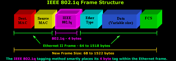
Source: https://www.firewall.cx/images/stories/vlans-8021q-analysis-1.gif
Hybrid Ports
-
-
- Hybrid ports allow network access AND transmit tagged traffic between two network devices
- Ports 2 through 5 in the diagram above are hybrid ports because...
- The ports are untagged on VLAN 100 to facilitate the virtualization server's own traffic
- But, the port are also tagged with the VLAN IDs of the VMs nested below to facilitate traffic from virtual switch (acting as a trunk)
- Hybrid ports allow network access AND transmit tagged traffic between two network devices
-
Trunk Ports
-
-
- Trunk ports connect two network devices, but do not provide access to end devices
- Switch <-> Switch
- Switch <-> Router
- When a destination MAC address does not exist on the switch...
- Trunk ports connect two network devices, but do not provide access to end devices
-
Untagged
- Untagged means that there is no 802.1q data in the Ethernet frame (no VLAN tags whatsoever)
- An untagged ingress Ethernet frame will assume the frame is coming from the PVID of the port
- The untagged ID usually matches the PVID assigned to the port
- Most standard devices such as laptop, desktops, and servers put untagged frames on the wire
- The switch uses the port PVID as the source VLAN for the ingress Ethernet frame
- Then, looks at the destination MAC address to see if it's in the CAM table for the same VLAN
- If the MAC doesn't reside on the switch...
- Tag the frame with the 802.1q VLAN ID based on the port PVID
- Flood the frame out on any known trunk port(s) that are tagged with the VLAN ID
- This is effectively broadcast traffic on a targeted VLAN
- Intermediary switches repeat this process of broadcasting the tagged frame on any trunk port(s) tagged with the VLAN until it reaches the recipient
- However, "untagged" also applies to "tagged" Ethernet frames
- If port 7 is untagged on VLAN 10, then...
- If an Ethernet frame tagged with VLAN 10 reaches port 7, the port will strip the VLAN ID off the frame
Practical Examples
Wired PC -> VM3
VM3 and PC are in the same subnet
SHOW / HIDE
- VM3 and PC are in the same subnet, so MAC address can be resolved with ARP
- ARP asks, who has IP address
10.10.10.x?
- ARP asks, who has IP address
- Device on Port 7 does an ARP broadcast to ask for the MAC address of
10.10.10.x- At this moment, the Ethernet frame has no 802.1q data, so it is untagged
- Switch sees the untagged frame and checks the PVID of Port 7
- PVID is configured with VLAN 10
- ARP broadcast is sent to any port configured with VLAN 10
- Any untagged ports on Managed Switch and with PVID 10 will receive an untagged Ethernet frame as part of the broadcast
- Any ports on Managed Switch that are tagged with VLAN 10 will receive an Ethernet frame with VLAN 10 tagged in the 802.1q heade
- Ports: 1, 2, 3 ,4, 5 all receive the broadcast because they are tagged with VLAN 10
- With respect to ports 2-5, the load balancing algorithm on bond0 will pick a single source port when processing the broadcast
- The tagged frame goes on the wire to:
- virtual switch
- firewall
- Firewall and Virtual Switch receive he tagged frame
- And, deliver the frames to any ports with PVID 10
- The ports strip the VLAN 10 tag and deliver to the respective host(s)
- VM3 receives the ARP broadcast and responds by creating an ARP reply
- Ports: 1, 2, 3 ,4, 5 all receive the broadcast because they are tagged with VLAN 10
- The ARP Reply is stamped with Wired PC's MAC address and completes its journey back
- At this point, the Ethernet frame is untagged
- Virtual switch notes the Ethernet frame is coming from PVID 10
- The destination MAC address is in the CAM table for VLAN 10 and is recorded as being on bond0 which is a trunk port
- Virtual switch associates the Ethernet frame with VLAN 10 and sends it up the trunk to Managed Switch
- Managed Switch receives the tagged frame for VLAN 10 and notes the destination MAC is in the CAM table for VLAN 10
- Managed Switch sends the frame to port 7
- Port 7 strips the 802.1q data and sends it onward to Wired PC
VM2 -> VM1
VM3 and VM1 are in distinct VLANs, 3000 and 1028 respectively
SHOW / HIDE
VM2 Needs Gateway MAC Address
- VM2 and VM1 are in distinct subnets, so the traffic must be routed
- VM2 sends an ARP broadcast for default gateway
10.30.30.1- Which MAC address owns
10.30.30.1? - At this point, the Ethernet frame is untagged
- Virtual switch sees the untagged frame and checks the PVID of VM2
- VM2 PVID is configured with VLAN 3000
- Which MAC address owns
- Virtual Switch will forward the broadcast to any other port configured with VLAN 3000
- Virtual Switch trunk port that runs up to bond0 is tagged with VLAN 3000
- Therefore, the Ethernet frame is stamped with VLAN 3000
- And is sent up the trunk, as well, to Managed Switch
- The load balancing algorithm on bond0 ensures the Ethernet frame only exits one interface
- ARP broadcast reaches Managed Switch
- Managed switch processes the broadcast in two ways...
- Sends the ARP broadcast to any ports with PVID 3000
- Any ports untagged on VLAN 3000 will strip the VLAN ID before egress
- The trunk port connecting to Firewall is tagged with VLAN 3000
- Stamp the Ethernet frame with VLAN 3000 and send up the trunk
- Sends the ARP broadcast to any ports with PVID 3000
- Managed switch processes the broadcast in two ways...
- Firewall receives the tagged frame
- Firewall strips the VLAN ID and forwards the frame to interface
igb1.3000, as it is the sole member of VLAN 3000
- Firewall strips the VLAN ID and forwards the frame to interface
- igb1.3000 prepares an ARP Reply back to VM2
- Stamped with destination MAC address of VM2
- Firewall looks at ARP table and sees destination MAC was last seen on igb1.3000
- Firewall associates the Ethernet frame with VLAN 3000, as this is VLAN ID of igb1.3000
- Ethernet frame is sent back down the trunk to Managed Switch
- Managed Switch receives tagged frame VLAN 3000
- Destination MAC is already in the CAM table from previous ARP broadcast, and noted to be on a trunk port connected to Virtual Switch
- The actual port would have been determined by bond0 selected interface from initial ARP broadcaast
- Sends tagged frame down the trunk to virtual switch
- Destination MAC is already in the CAM table from previous ARP broadcast, and noted to be on a trunk port connected to Virtual Switch
- Virtual switch receives the tagged frame
- Virtual switch notes the destination MAC is for VM2
- VM2 PVID is 3000, which matches, VLAN ID is stripped and delivered to VM2
VM2 -> VM1
- VM2 wants to send application layer data to VM1
- Source MAC: VM2
- Destination MAC: igb1.3000 (received earlier in ARP Reply)
- Source IP: VM2
- Destination IP: VM1 (10.128.128.x)
- Untagged frame is put on the link and enters Virtual Switch
- Virtual Switch notes destination MAC is in CAM table for VLAN 3000, and was last seen on bond0
- Virtual Switch associates the Ethernet frame with VLAN 3000 and sends up the trunk on bond0 with VLAN 3000 tagged in the 802.1q headers
- bond0 uses load balancing to choose a port to send the Ethernet frame on
- Managed Switch receives the tagged frame and notes the destination MAC address is in the CAM table for VLAN 3000
- Destination MAC is on Port 1 (the trunk)
- Managed Switch sends tagged frame up the trunk to Firewall
- Firewall receives the tagged frame and notes the destination MAC address is igb1.3000
- Firewall strips the 802.1q data from the frame and sends to igb1.3000
- igb1.3000 receives the untagged frame and inspects the TCP/IP data
- Destination IP: VM1
- This packet needs to be routed elsewhere
- igb1.3000 checks its routing table and 10.128.128.x is in the routing table
- Firewall prepares a new packet to go down VLAN 1028
- TCP/IP data
- Source MAC: igb1.1028
- Destination MAC: VM1
- Source IP: 10.128.128.1
- Destination IP: 10.128.128.x
- Firewall already has the ARP data in its cache for 10.128.128.x (VM1)
- Destination MAC for VM1 was last seen on the trunk port
- Firewall tags the frame with VLAN 1028 802.1q data and sends to Managed Switch
- TCP/IP data
- Managed Switch receives the tagged frame
- Destination MAC is in the CAM table as whichever switch port -- 2 through 5 -- that load balancing algorithm last used for VM1
- Managed Switch sends the tagged frame down the trunk to Virtual Switch
- Virtual Switch receives the frame tagged with VLAN 1028
- Destination MAC is in the CAM table for VLAN 1028
- PVID for Destination MAC is VLAN 1028, so strip VLAN ID, and deliver frame